Common emitter connection (or ce configuration) Draw circuit diagram of cb configuration Component. npn transistor diagram: transistor academics easy bjt
Solved A circuit using the BJT is shown in the below figure, | Chegg.com
Common emitter configuration of bjt Bipolar junction transistor (bjt) basics Amplifier circuit schematic diagram
Bipolar junction transistors (bjts)
Bjt circuit diagramDraw circuit diagram of cb configuration Draw circuit diagram of cb configurationCommon emitter characteristics circuit diagram.
Bjt circuit transistor bipolar junction basic ce analysis figureCe configuration circuit diagram Bjt transistor bipolar junction circuit electronic transistors unit applications components101 circuits understanding rantle controlledCommon emitter amplifier and transistor amplifiers.

Transistor bipolar ebook bjt junction electronics tutorials its basic amplifier switch will
Solved part 1: ce bjt amplifier 1. construct the circuit inCircuit diagram of bjt Bjt amplifier bipolar junction transistor analog transistors bjtsBjt ltspice.
Output configuration ce curve characteristic common emitter collector transistor base cc current characteristics input graph connection circuit amplifier region activeBjt/ce configuration using ltspice Hybrid model (equivalent circuit) for bjt in ce configurationSolved problem: transform the following ce bjt to the ac.

Bjt ce amplifier circuit diagram
Input common configuration emitter ce characteristic curve characteristics output circuit base connection collectorBjt transistors: symbol, basics, construction, working & applications Bipolar transistor tutorial, the bjt transistorTransistor common emitter circuit bipolar bjt amplifier configuration electronics tutorial.
Bjt configurationsLect7:bjt:-trick to draw input output characteristics of cb, ce and cc Solved for the following bjt circuit shown (ce circuit) withCommon emitter diagram.

Solved a circuit using the bjt is shown in the below figure,
Bjt configurationsDraw the typical input and output characteristic of an n Circuit transistor bjt current amplification containing given questions stackCommon emitter connection (or ce configuration).
Types of transistors and their usesTransistor diagram npn component academics bjt easy clipart Comparison of cb, ce and cc configurationsBipolar transistor ebook.

Working of ce amplifier
Common emitter pnp transistor circuit diagramAmplifier transistor emitter amp amplifiers .
.


Comparison of CB, CE and CC Configurations - BJT Configurations - YouTube

Types Of Transistors And Their Uses
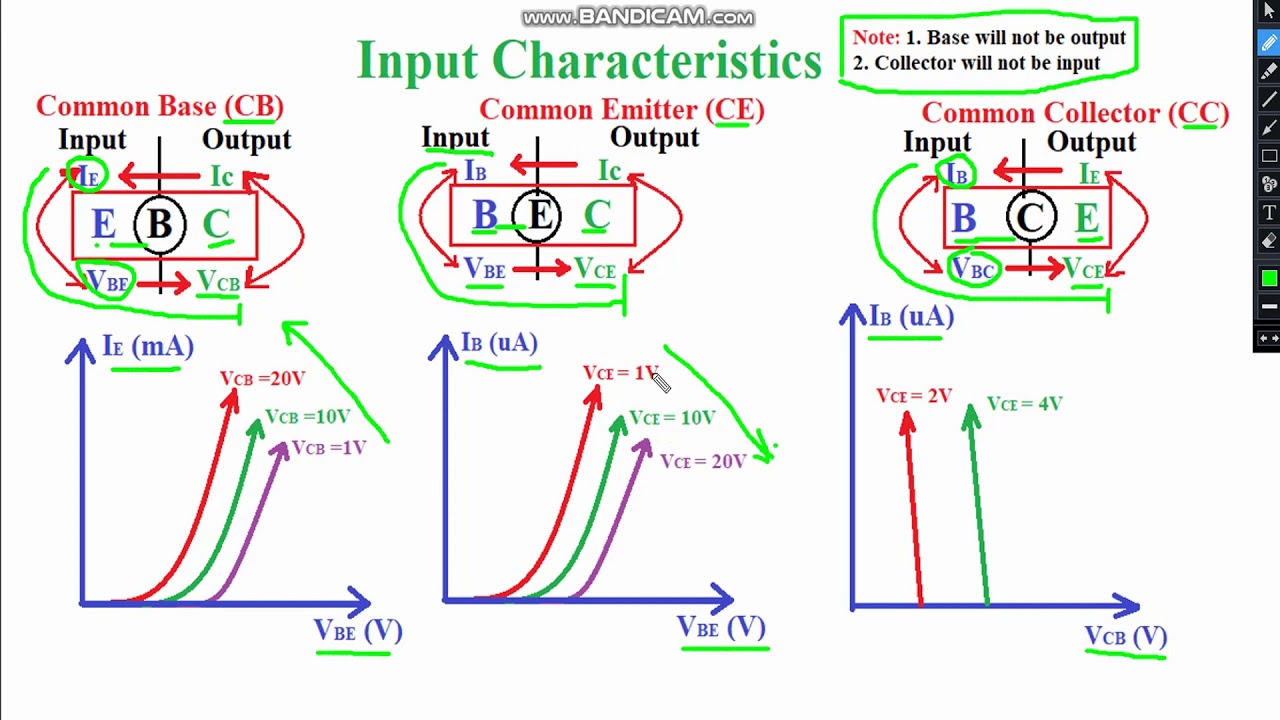
Lect7:BJT:-Trick to draw Input output Characteristics of CB, CE and CC

common emitter diagram - IOT Wiring Diagram

Bjt Circuit Diagram

Common Emitter Amplifier and Transistor Amplifiers

Hybrid Model (Equivalent Circuit) for BJT in CE Configuration - YouTube